Motor Focuser
I can now remotely control almost all the functions of my telescope and its mount. But for focusing my DSLR attached to the telescope I need to go to the scope with the laptop and drag the USB cable with me just so I can see the LiveView image of the camera on the laptop while adjusting focus on the telescope.
So I need to motorise my focuser so that I can focus remotely. This is what this page is all about.
I have chosen to use the SGL_Observatory_Automation focuser project. This is an Arduino based motor focuser with ASCOM driver on the PC side. Links to the project are at the bottom of this page.
This is an ongoing project and I will document my progress on this page.
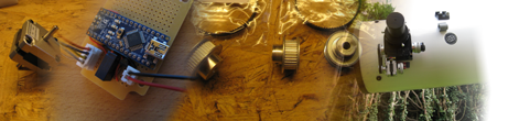
Here is what I have so far (as of 9 September 2011):
One stepper motor
A handful of timing belts and pulleys
and an EasyDriver stepper driver board
Here is the first test to drive the stepper from an Arduino. IT MOVED!!! :-)
First update 12 September 2011
Over the weekend I have worked on the mechanics. I made a bracket that allows the stepper motor to be attached to the focuser. Another bracket holds the EasyDriver board and the 4P4C connector socket.
Here is the stepper attached to the focuser. This also shows the timing belt and pulleys.
The next step was to make a bracket that will hold the EasyDriver board and the connector 
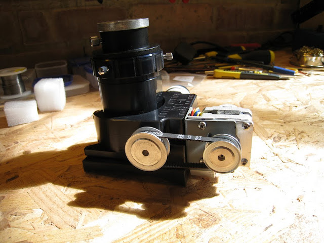
This is the whole stepper and driver module
And here is everything put together
It does look a bit like a steam engine, doesn't it? 
I've had some problems with the stepper not being able to turn the focuser occasionally. The problem seems to be the 10:1 gearing on the other side of the shaft not going very smoothly. So I took that apart and cleaned and re-greased it. I was surprised by how that gearing actually works. I was expecting to see a few little gears. Instead I found this:
There were some metal bits/filings in there that probably got in between the metal piece on the left and the bearing balls preventing it from turning properly. I cleaned that out and applied new lithium grease. I think it was also put together too tightly requiring more torque when turning. This is OK when operated by hand but the stepper didn't quite cope. I've left it a little more loose when I put everything back together. It is now turning much better but still has moments when the stepper doesn't have enough force and slips.
I've ordered a bigger pulley for the focuser side and a longer belt. Hopefully a higher gear ratio will fix the remaining issue.
Regarding the EasyDriver board, I have been told that it would be rather dangerous if the stepper motor got disconnected while the EasyDriver was powered. Apparently this would instantly destroy the driver chip. That is why I decided to put the EasyDriver board right next to the stepper. I didn't want to take the risk of accidentally unplugging the motor cable before powering down the driver. After a long night on the scope you never know... 
The Arduino controlling the stepper will then be located in my Power and Data Box. I need 4 wires between the Arduino and the EasyDriver - 12V for the motor, Step and Direction signals and, of course, Ground.
Next update 14 September 2011
Yesterday the bigger pulley and longer belt have arrived. I installed them on the focuser and now everything is moving fine. There is no more slipping.
(There is a video of it moving on the Picasa gallery, see link at the bottom of this page)
The smaller pulley on the stepper has 32 teeth and the larger one on the focuser has 60 teeth. This almost gives a 2:1 gear ratio. The belt is a 100 teeth MXL belt. The shaft centres are 54mm apart.
Next update 16 September 2011
Last night I build the "controller board". It consists of an Arduino Nano and a simple relay circuit. This is the test setup. The finished version will not feature sello tape to protect against short circuits! 
The plug on the left is the input for the 12V supply for the stepper / EasyDriver. The 4 wires on the right go to the EasyDriver / focuser. The blue board is the Arduino Nano (it is even smaller than the already small EasyDriver board!!!). The stuff above the Nano is the relay and it's circuitry (a NPN transistor, a 6k8 resistor and a protection diode). This relay switches the power to the EasyDriver on and off; controlled by software in the Arduino. The Arduino itself is powered from the USB port.
Here is it a little closer: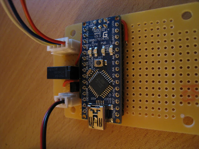
I have created a circuit diagram which is available for download at the bottom of this page.
Later that night I connected everything to the computer for the first time. After a few small problems I got everything working just fine. I also changed the Arduino program (called a sketch) so that the EasyDriver is powered down automatically after 20 seconds of inactivity.
Next update 18 September 2011
Over the last few days I have made more progress.
The Controller board has been installed inside the Power and Data Box. I used 4 5mm brass hex stand-offs to hold the board in place: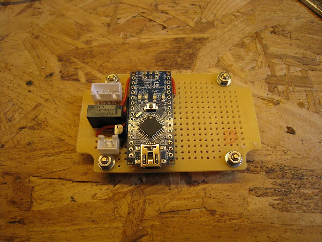

Here it is installed inside the Power and Data Box. It was a slight oversight to install it so the USB connector is at the top. I ordered a different cable with an angled mini-USB connector.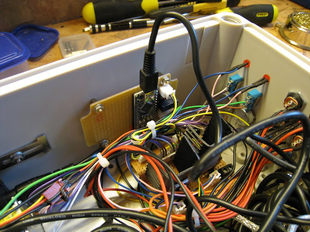
On the output side of the box I added a 4P4C (RJ10) connector for the cable going up to the focuser.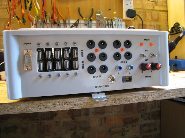
Next I mounted the focuser back onto the telescope.

Then I added the new cable to the "cable management"
So this project is almost done. All that is left to do ist to test it properly on a clear night...
Next steps:
- test during a proper imaging night
As usual, more pictures in my Picasa gallery here:
https://picasaweb.google.com/117034922665750406576/201109MotorFocuser
External links
The SGL Observatory Automation project
Yahoo! discussion group
http://tech.groups.yahoo.com/group/sgl_observatory_automation/
Project discussion on Stargazer's Lounge (SGL) forums
http://stargazerslounge.com/diy-astronomer/106144-arduino-focus-control-cloud-sensor.html
EasyDriver information
http://schmalzhaus.com/EasyDriver/
Downloads