8" Lightbox MK I
I wanted to get started with astro photography, so I needed a light box in order to shoot some flat frames. I've seen a few different designs around but I decided to see whether I could use the background lighting of an old 14" laptop TFT panel I had lying around. Some time ago I had already converted this display panel to work like a "regular" flat screen monitor.
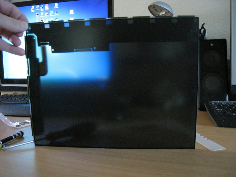
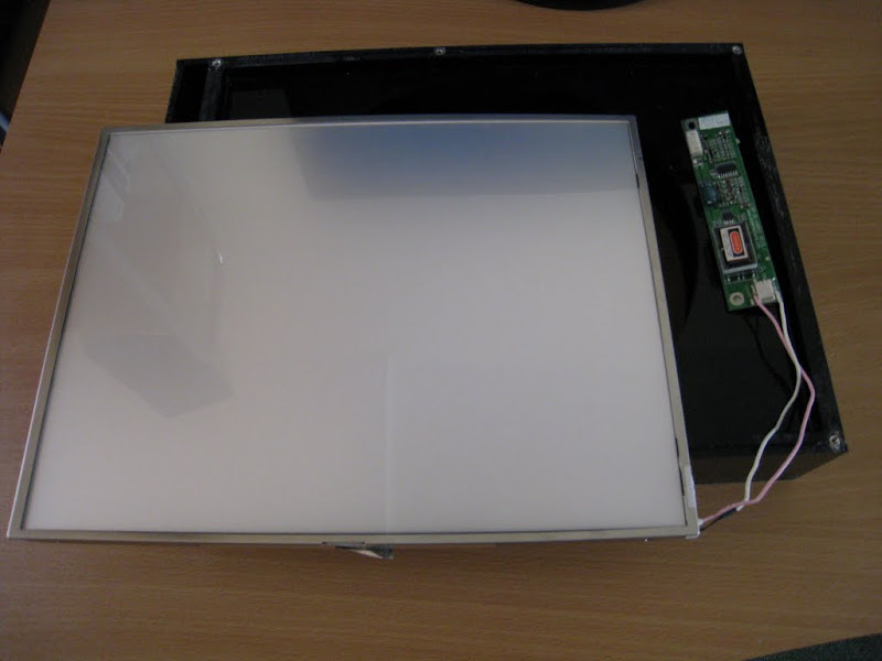
The first thing to do was to check whether the actual TFT display can be separated from the background light. So I started taking the panel apart and found that this was indeed possible and rather easy to do.
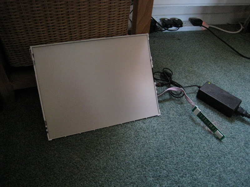
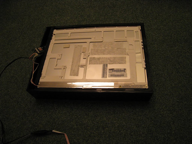
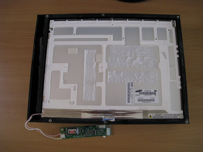
Here is a picture of the background light with the TFT panel removed:
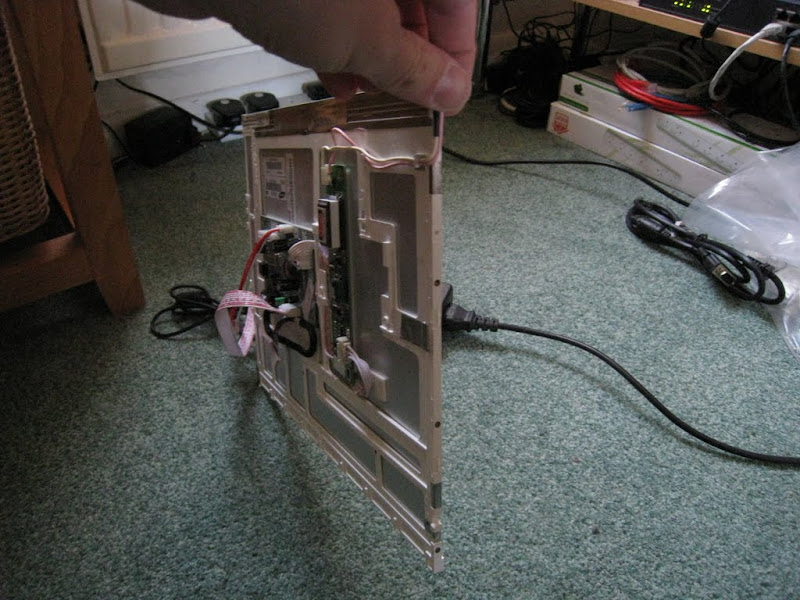
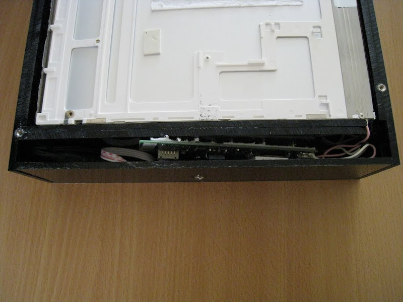
View from the back with the VGA controller board and the inverter board (power supply for the background lighting lamp):
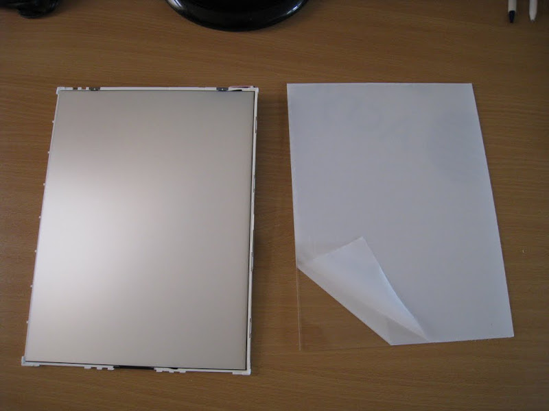
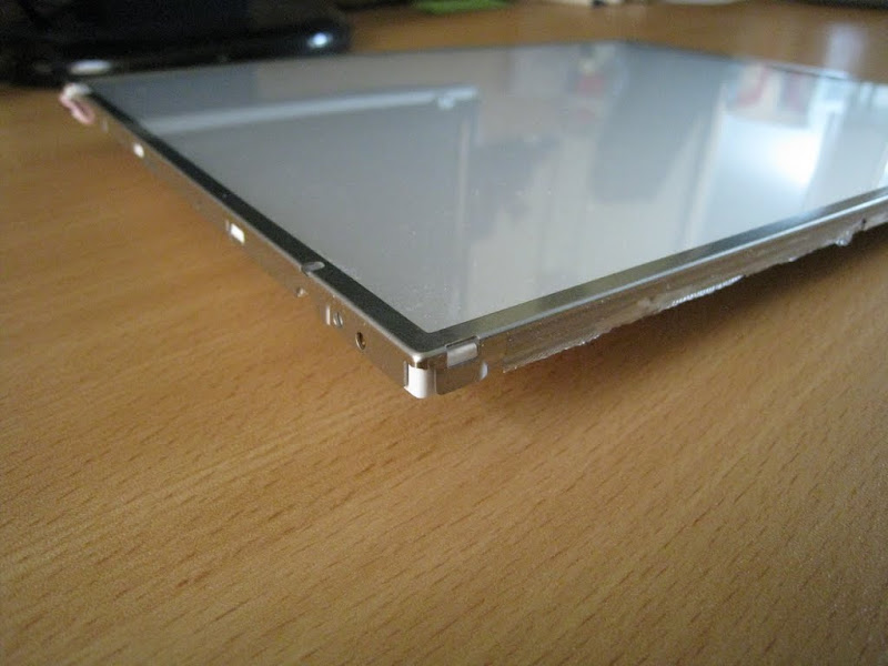
This is the actual TFT panel that I removed:
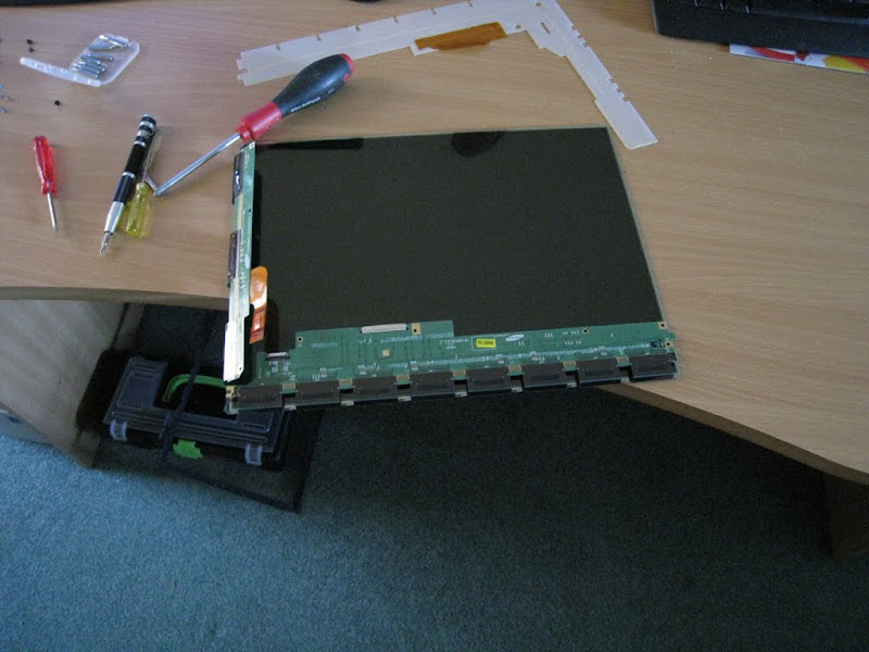
It still works as well: ;-)
I think I'll keep that somewhere safe. You never know when you might need a transparent TFT display... :D
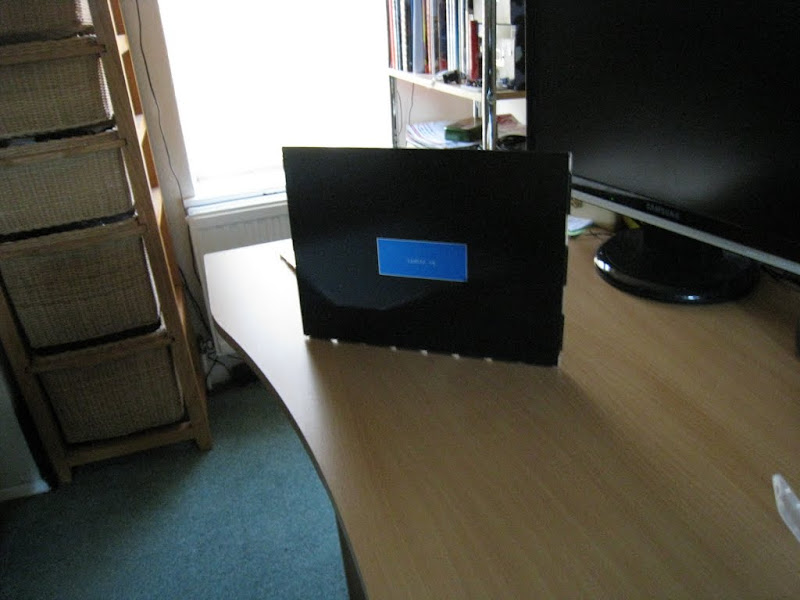
The next step was to see whether the light still works.
This is when I discovered the first (small) obstacle. Since there was no video signal, the controller board, which also controls the power to the lamp, went into power safe mode a few seconds after switching it on. I had to be really quick taking the picture above.
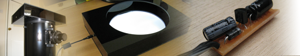
So I checked the pin-out of the inverter board. Thanks to the Internet that was rather easy to find. It turned out that the inverter board requires 12V for generating the actual power for the lamp (which lies in the region of 600V, by the way). The inverter has another 2 inputs; one is the lamp enable pin and the other controls the brightness of the lamp. Luckily, no voltage on the brightness means maximum brightness and supplying higher voltages dims the light more and more. Since I wanted maximum brightness, I could just ignore that pin.
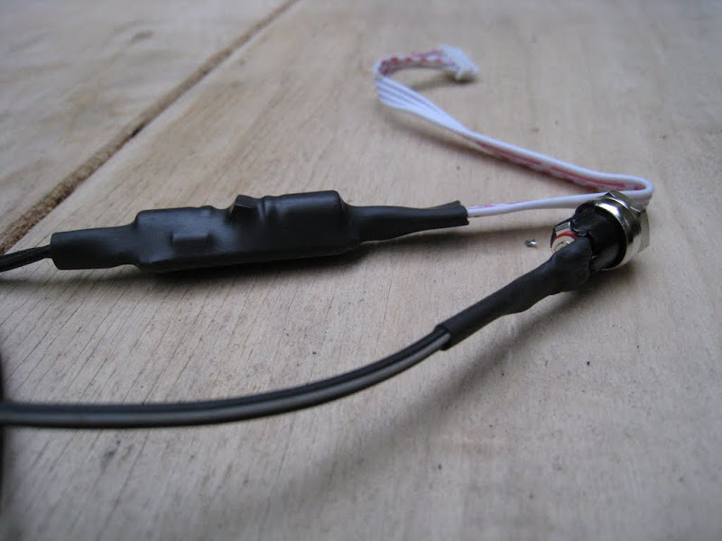
Not so lucky with the lamp enable. Unfortunately that input requires 5V to switch on the lamp. So I had to get 5Volt from somewhere in addition to the 12V for the lamp. I decided to do it properly and built a small circuit with a fixed voltage regulator (78LM05), a diode and 2 capacitors. This ended up looking like this:
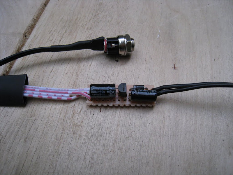
Then I protected it with a bit of heat shrink:
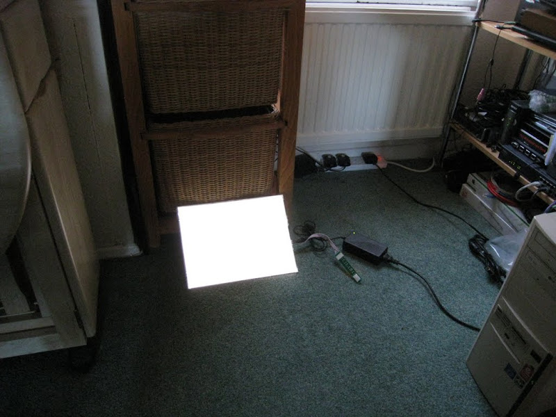
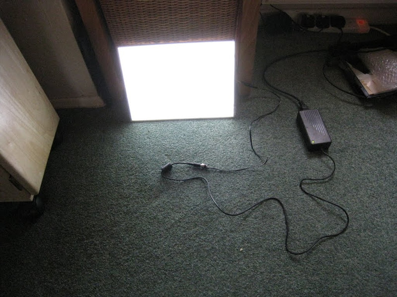
A quick test shows that the light now stays on as long as I want:
OK, that's the "electronics" sorted out.
The stuff that distributes the background light evenly behind the TFT panel was made up of several (more or less loose) sheets of plastic foil that needed to be protected. So I replaced the TFT panel with 2mm thick clear acrylic sheet that I had cut to size from ebay.
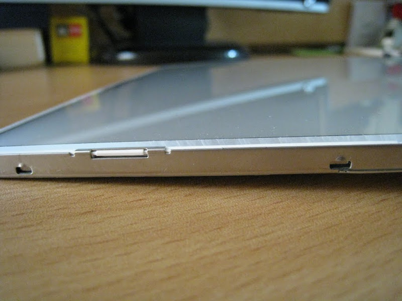
Then I put the metal frame back on. The 2mm acrylic was a bit thicker than the original TFT panel but the frame just fit fine.
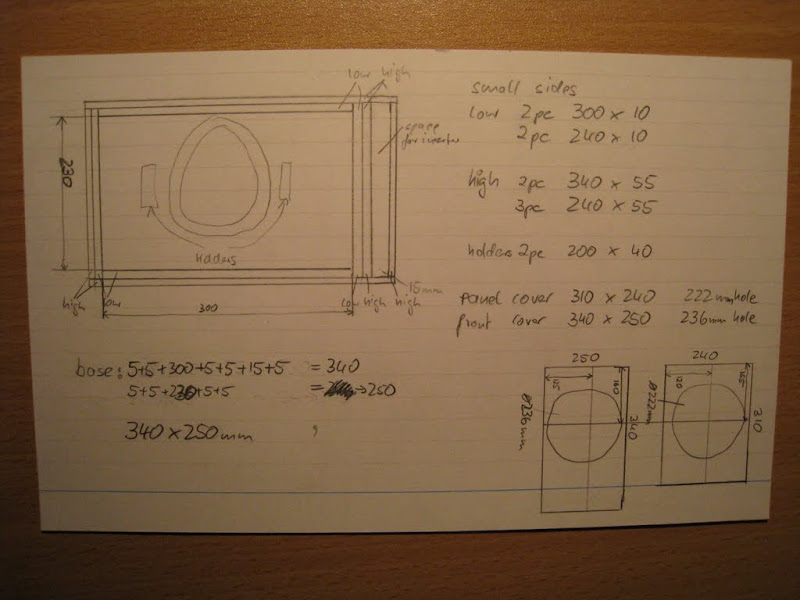
Next step: design a case / housing for the panel that allows for easy mounting onto my 8" Newtonian telescope. I decided to use black 5mm thick acrylic sheet for the housing. That would look best, be cheap and easy to put together.
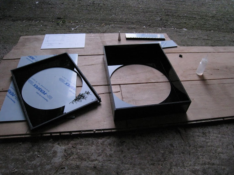
Here's the "work sheet" where I designed the casing and calculated the dimensions of the acrylic pieces I would need.
I've ordered the acrylic on ebay and had them cut to size. Here's what I got:
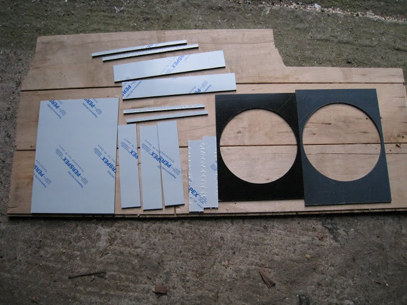
At this point I realised that, if I wanted the base sheet removable, I wouldn't be able to build the box from the base sheet up as I had planned. I would have to start from the top and build it without the base attached. It was a bit awkward but I managed to do it. Lesson learned for next time...
In order to "glue" the bits together I use a method called solvent welding. You just hold the bits together at a right angle and apply a bit of solvent. This "melts" the acrylic of both pieces and dries up rather quickly again. A few moments later the 2 bits are basically one piece of plastic and the solvent has completely evaporated. No ugly glue bits remaining. Because this needs to be done very quickly before the solvent dries up I wasn't able to take any pictures of that process. Here is a Youtube video that shows it nicely: How to glue Acrylic
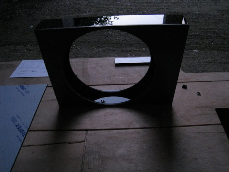
### Since I used very glossy black acrylic it turned out to be very difficult to take decent pictures of it. I hope you can recognise at least some of the shapes. ###
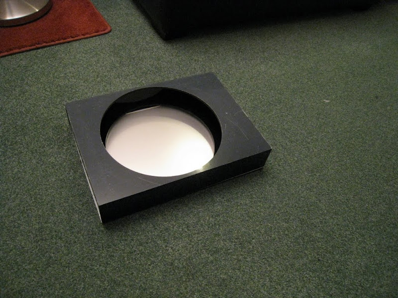
Here is the first part done:
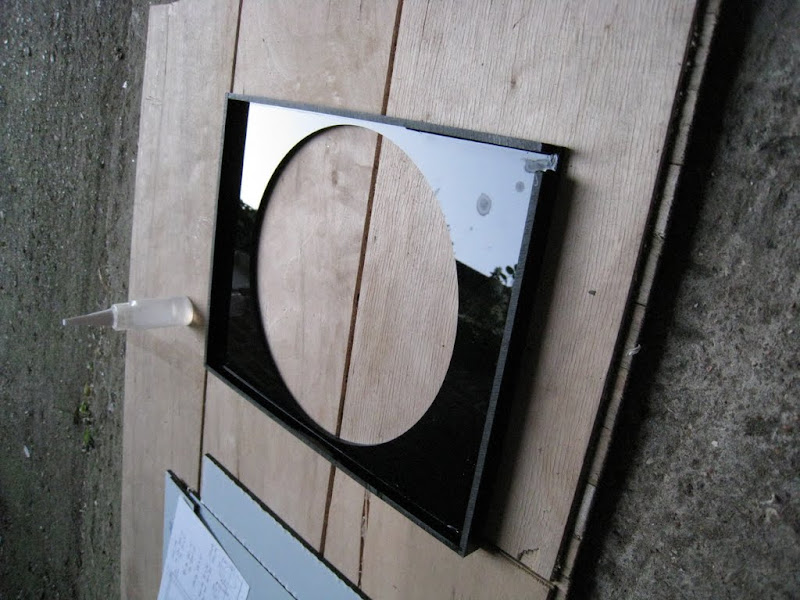
The stains you see is what happens if solvent drops get onto the acrylic. So be careful!
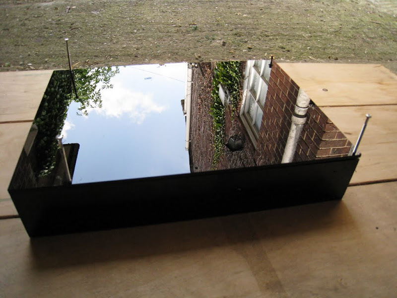
Making progress:
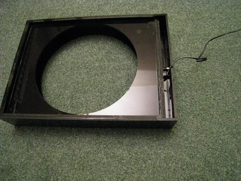
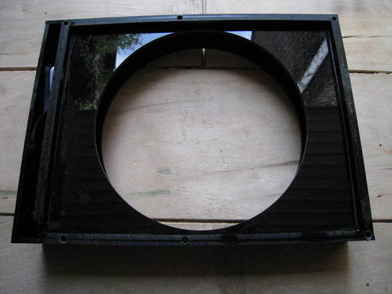
The panel then fits in like this. My digital camera really had a hard time trying to get the lighting right.
Next day: Now that the glueing is definitely dried up and hardened I can drill some holes and glue some nuts in so that I can then attach and remove the acrylic sheet at the back with screws.
I've put the back plate on the box and drilled one hole (diameter just a little bigger than the screws that are to be used) in the right place through the back plate and about 1cm into the box walls. Then I put a long screw in to keep the holes aligned. I repeated that making 6 holes.
Then I used a bigger drill and widened the holes in the box walls.
The holes needed to be big enough so that I can glue in these....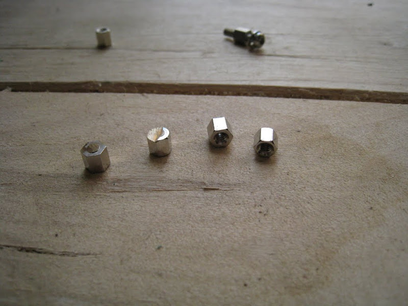
... with that:
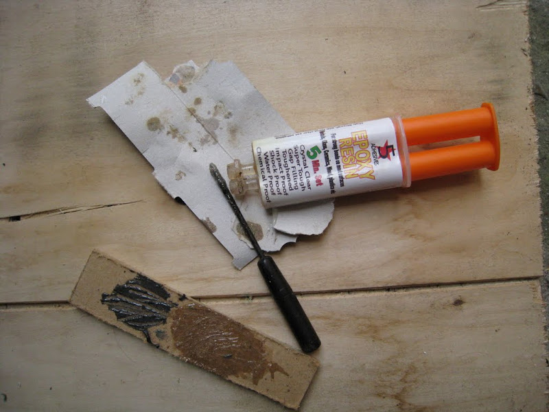
So I mixed the glue and filled some in each hole. I also put a screw in each nut. This makes it easier to hold the nut and move it so that it's straight. It also prevents glue from getting inside the nut.
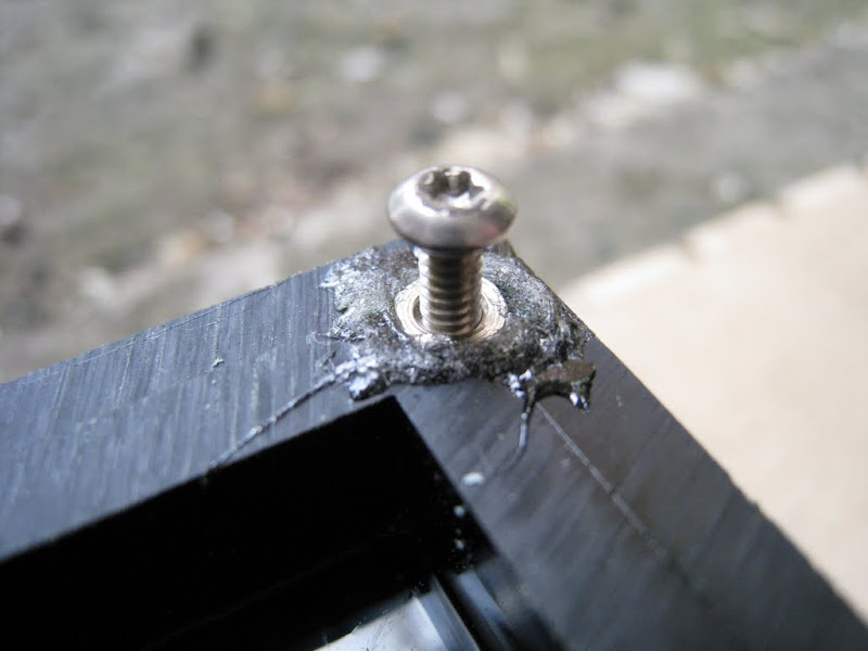
When the glue had set but not completely hardened yet, I used a standing knife to get rid of the excess glue.
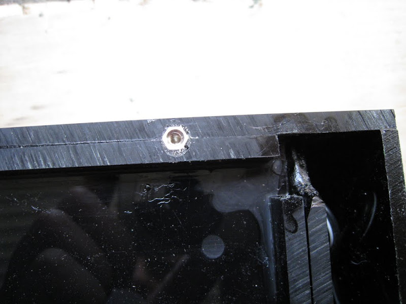
Here it is with all 6 nuts glued in, ready to attach the back plate:
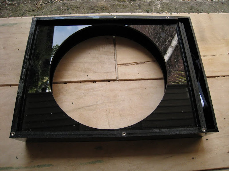
Here it is closed:
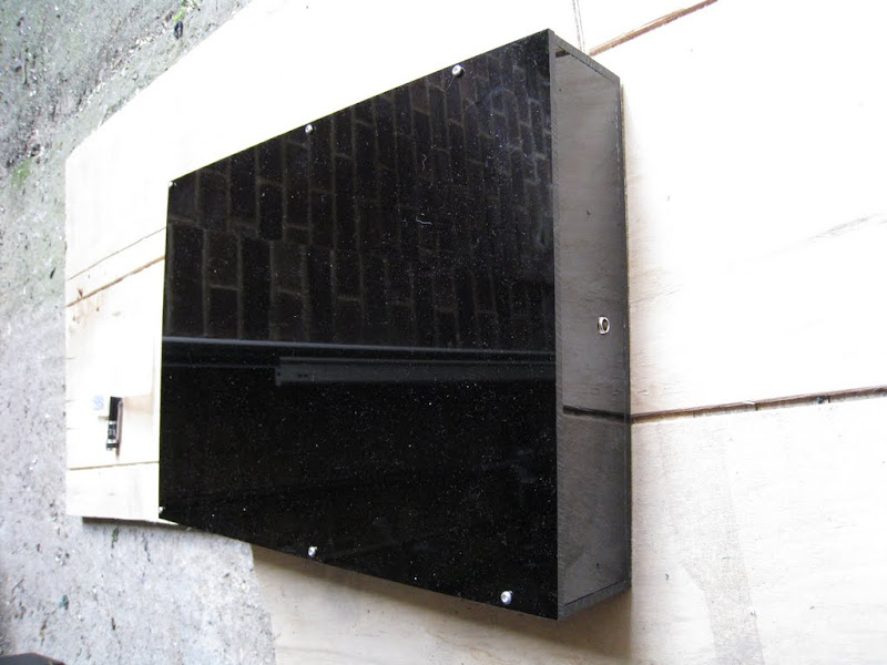
Now all that was left to do was to insert the panel ...
... tuck away the "electronics" ...
... and switch it on:
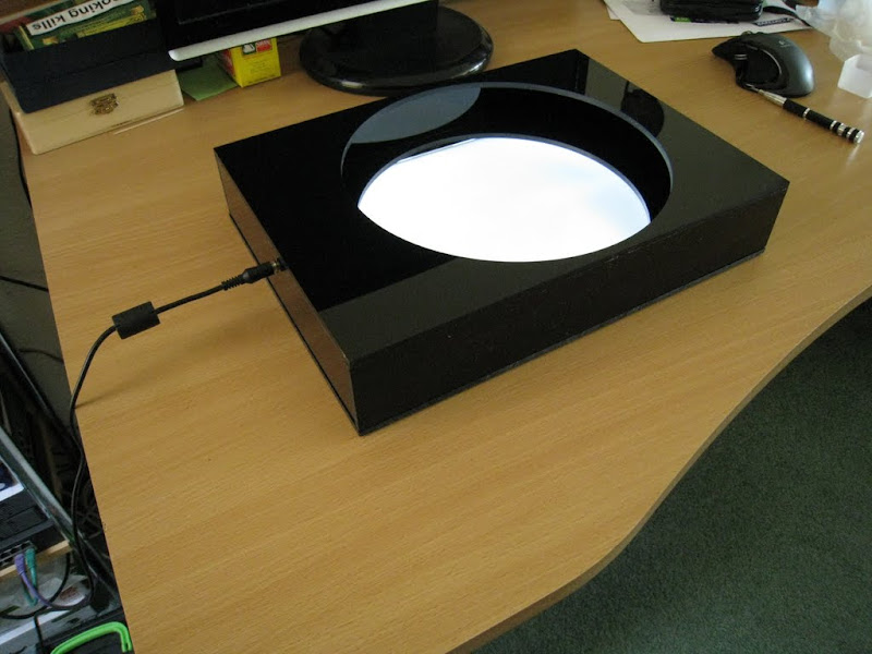
Yay!! It works... ;-))
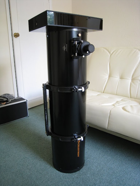
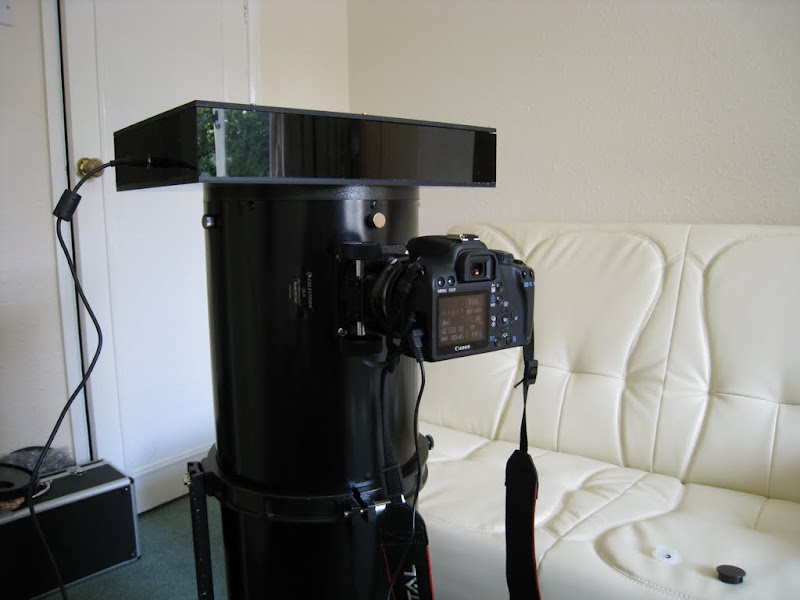
Next I got out my scope and tried the lightbox on the scope:
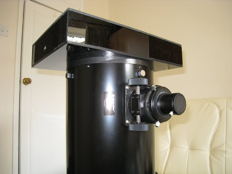
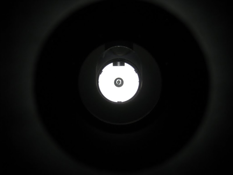
Looking through the focuser draw tube it looks like the lightbox would make a good collimation tool too.
Finally, I couldn't resist taking a few flat frames to see what they would look like.
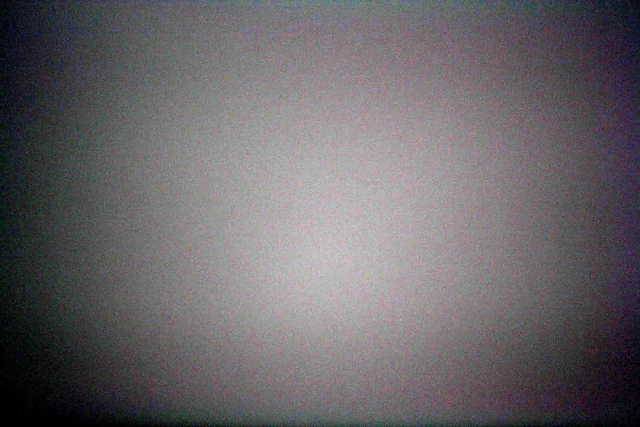
This is one of the unmodified flat frames:

OK, looks boring, I know. To show that there is indeed some information in it, I have stretched the histogram to exaggerate the subtle differences in the original image. Out came this:
Not had enough pictures yet? There are a lot more pictures of how I build the lightbox in my gallery here:
http://picasaweb.google.com/chris.yesyes/Lightbox#