Modding an SPC880/900 webcam for long exposure and AmpOff
After presenting my modded webcam in the DIY section of this website and on the Stargazer's Lounge forums (SGL) I've had quite a few requests from fellow astronomers asking whether I can do the mod for them. While doing all these mods I've taken lots of photos and will document the build here for anyone who wants to do the mod themselves.
This is the standard LX and AmpOff mod (sometimes referred to as the SC1.5 mod) as described on numerous other websites with 2 exceptions:
- It uses 3 small NPN transistors instead of the commonly used integrated circuits
- More importantly, it does away with the extra serial port cable (sometimes parallel port cable) that the other mods require. This modded webcam includes a USB hub and a USB to serial port converter in the project box. As a result there is only one cable coming out of the modded webcam - the original USB cable from the webcam.
Please note that the following photos are not all of the same modded webcam. The colour of all non-USB wires changes from mod to mod. So when you copy this build don't go by the colours of the wires but use the diagram below.
Overview
This is the diagram of what we are trying to achieve. This shows how everything will be connected together. It also shows why no additional serial cable is required. The USB-to-Serial converter is hidden inside the box. The USB hub is required because we need 2 USB ports, one for the webcam and one for the converter.
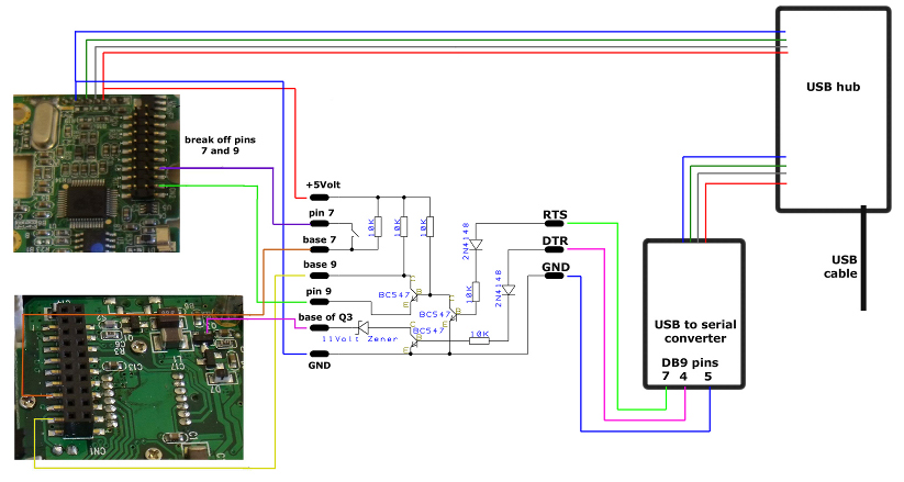
A larger version of the diagram is available for download at the bottom of this page.
Please note there is a mistake in the circuit diagram. The diodes are 1N4148, not 2N4148!
The Box
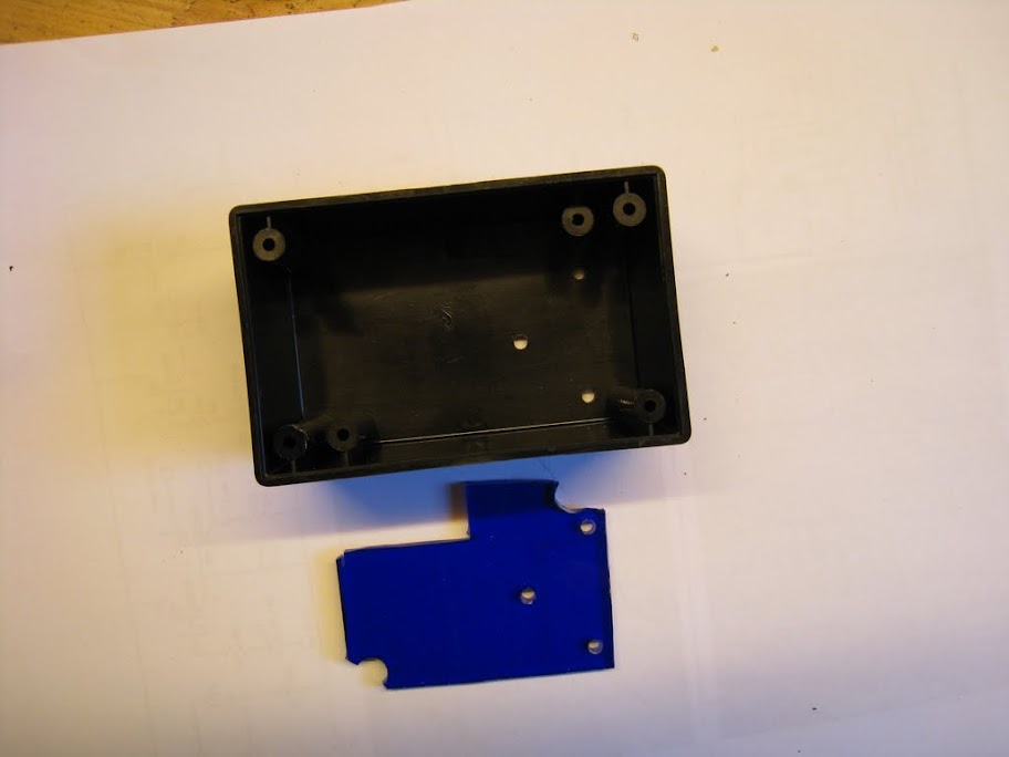
OK, let's start with the box that will house the modified webcam. I'm using 53 x 83 x 35mm ABS boxes with aluminium lid at the back. The boxes also come with a matrix PCB that fits nicely inside the box but I'm not using that for the mod.
Since I've been doing several of these mods recently I've made myself a template for the front holes; 2 mounting holes and 1 that will be drilled out bigger (12mm) for the nosepiece thread.

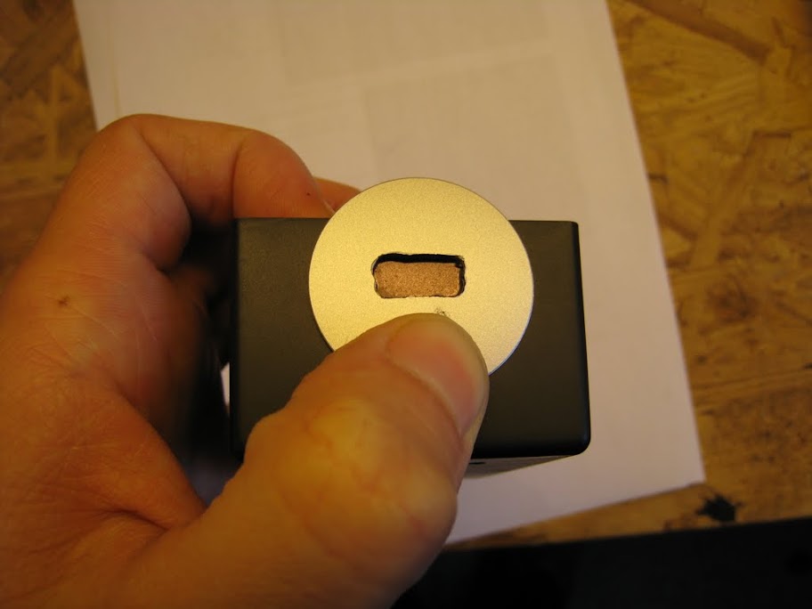
That's the front done. Next I cut the holes for the switch and the cable clip for the USB cable. First I mark where the holes need to go. Again, I use a template and a CD marker pen for the switch hole.
This area needs to be cut out.

On the opposite side I mark the area where the cable clip will go. This needs to be a tight fit in the end in order to hold the USB cable properly. So better begin a bit too small and then make it bigger step by step until it fits.

Then I drill a 4mm hole into the area where the switch hole will be. This is to allow the router bit of my rotary tool to fit in and get a starting point.

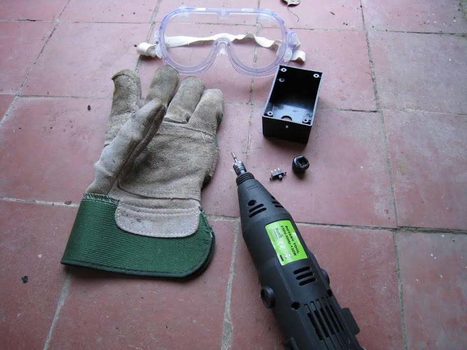
Then I cut the holes using this equipment. I wear the glove on the hand I'm holding the box with, in case the tool slips. And don't forget the safety goggles as there might be bits of plastic flying about.
Here is the result.


The mounting holes on the miniature switch I'm using are so small and close to the body of the switch that I was not able to find any screws and nuts that would fit. So I just used a few drops of Super Glue.

And here we go... 3 boxes prepared.
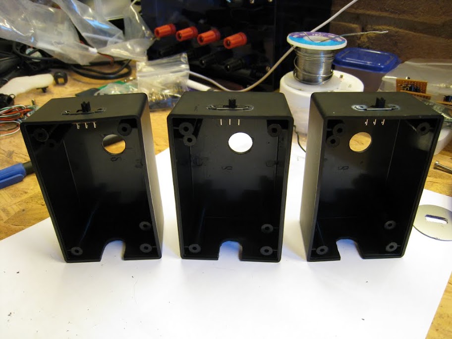
The white residue from the glue as seen on the top of the right box can be easily wiped off with a cloth.
The Electronics
The next step is to prepare the "stack" of electronics required for the mod. This consists of one 4-port USB2.0 hub, one USB-to-Serial converter and the self-made LX and AmpOff circuitry.
The USB hub board has been removed from a cheap USB hub with external connectors.
Before:

After:

The USB-to-Serial converter board has been removed from one of those USB-to-Serial cables. Make sure you use a converter for which the manufacturer supplies drivers for the Operating System you intent to use the modified camera with. I chose a Prolific PL2303 based converter as Prolific offer drivers for Windows 7 x64. Many of the cheap converters do not work on 64bit Operating Systems.
So I took the USB-to-Serial cable and removed the molded plastic and de-soldered the 9-pin serial connector. I ended up with this:

The 5 solder points on the bottom left are the USB connection (Vcc, D-, D+, GND left to right). On the right are serial pins 1-5. Pins 6-9 are on the other side of the board.
Next I solder 3 short wires to the serial port side of the converter, pins 4 (DTR), 5 (GND) and 7 (RTS). I solder them towards the inside of the board. This is to avoid bending and/or lifting the solder pads later.


Then I need to make the LX and AmpOff circuit board. The board needs to contain the following circuit.
Again, there is a mistake in the circuit diagram. The diodes are 1N4148, not 2N4148!

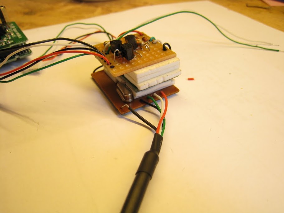
First I prepare the strip board.

Then I solder the components to the board. I also mark the holes that I will later solder wires to. The connections on the board follow the same layout as the circuit diagram above.

Here is the layout of the stripboard that shows a bit better what goes where

The 3 boards will be stacked on top of each other. I use double-sided sticky pads like this:

Make sure you don't cover the solder points as you still need to solder some wires there.
Another layer of sticky pads go on the top side of the USB hub board.

Then just stick both boards together.

Next I solder the USB side of the converter to one of the USB ports on the hub using the USB wire colour convention
red - Vcc
white - D-
green - D+
back - GND


Then on top of the converter board goes another 2 layers of sticky pads.

Then I cut the wires from the serial port to length and solder them to the LX circuit board. I add another wire (red) for the +5V supply for the LX circuit. This will go to the +5V output on the hub.

Then I stick the LX circuit board on top of the converter board using 3 layers of sticky pads in total to compensate for component heights.

Next I solder 2 wires to the LX board that will later go to the switch on the box.

That's the electronics done for now.
The Camera
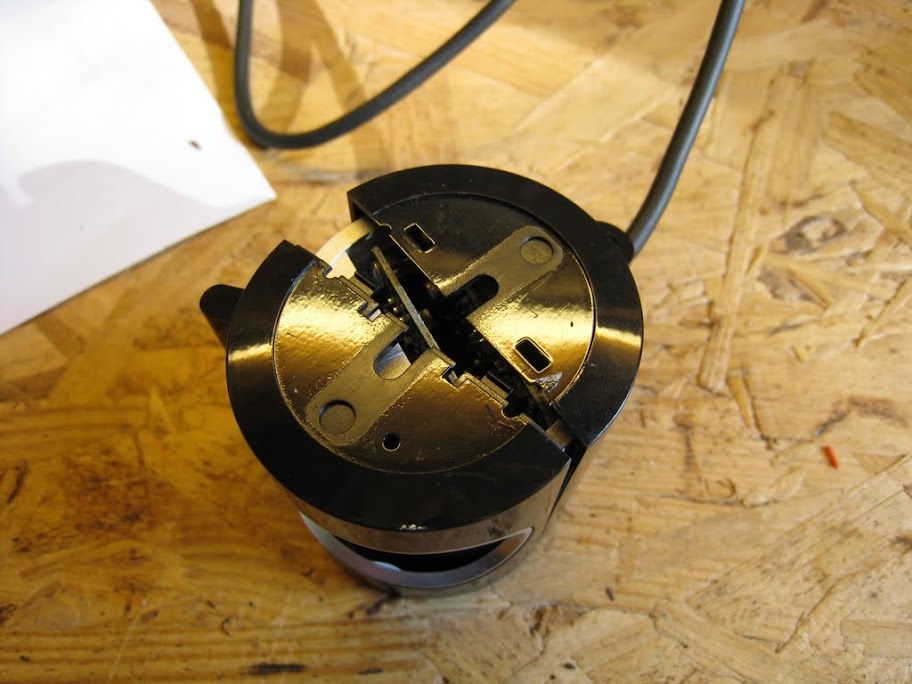
First the webcam needs to be taken out of its plastic housing. The silver focus ring on the front comes off by pulling on it. Sometimes I need to use a screwdriver as a lever. Then unscrew the lens.

The silver sides are attached with sticky tape. I use a knife to lift it. You are probably not going to use that housing any more, so it doesn't matter if you scratch it.

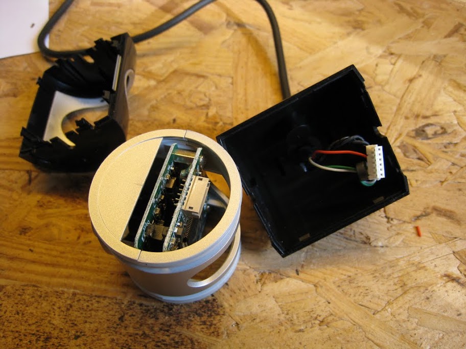
Use a small, flat screwdriver to push the clips in and pull apart the black plastic.

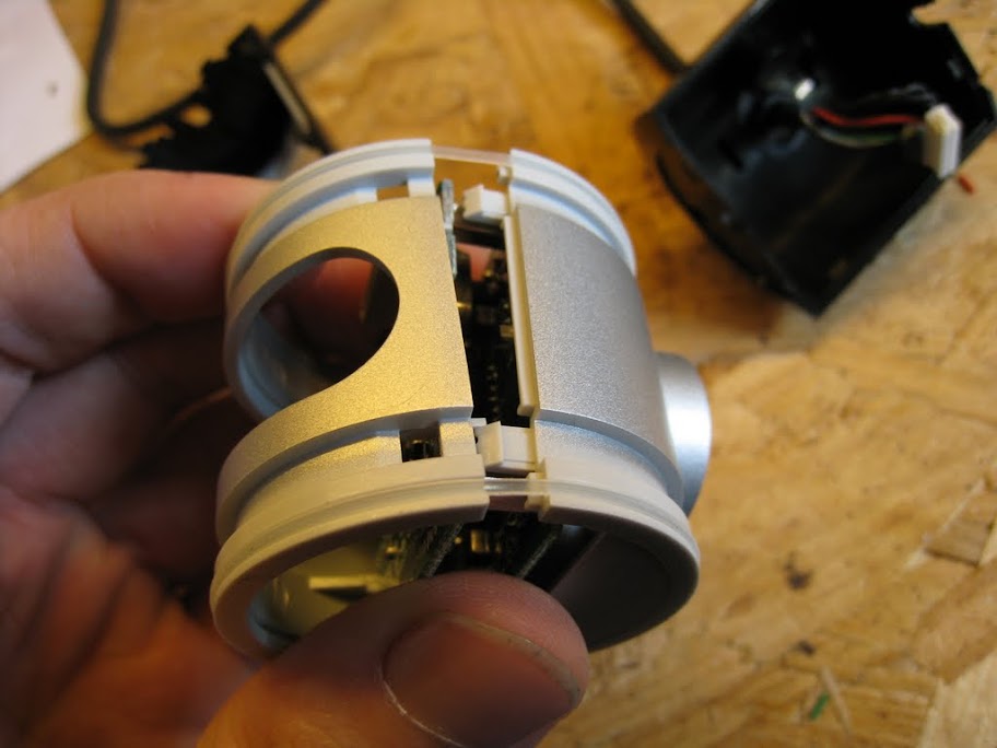
Once the black front plastic is off, unplug the USB cable from the webcam and take out the inner grey part.
Again, use a screwdriver to open the clips. Remove the rubber rings.

Unscrew the 2 tiny screws to get the last piece of plastic off.
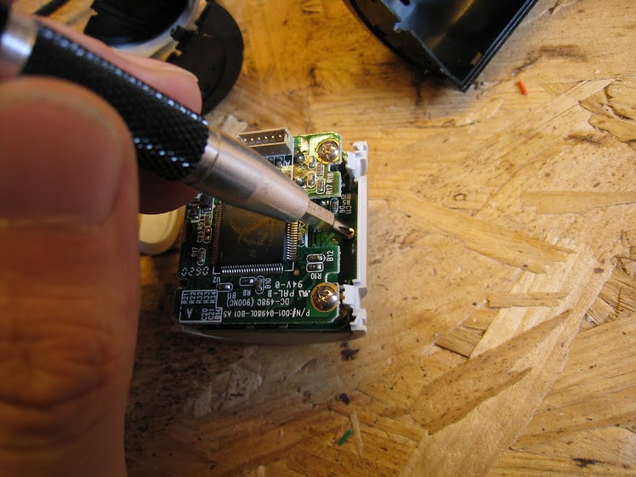
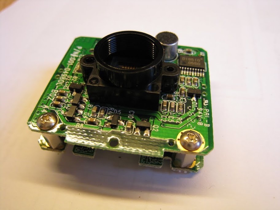
Now we have the bare camera.
Then, the first thing you want to do is to cut the track to the annoyingly bright white LED. We don't want any bright lights in our box. Don't cut too deep. This is a multilayer board and you don't want to scratch as deep as the next layer.

Then unscrew the 4 larger screws (2 on each side) and separate the 2 boards.

Next carefully break of pins 7 and 9 of the pin header connector as shown.

Then comes the tricky part. You need to solder a wire to the tiny, tiny Base pin of transistor Q3 on the sensor board. I found this to be the most challenging soldering task of the whole project. A steady hand is required. I use the 2 larger capacitors next to the transistor to hold the wire in place. Don't use too much solder. You don't want to accidentally connect it to that tiny capacitor to the left.

Then solder 2 wires to pins 7 and 9 and another 2 to base 7 and 9.
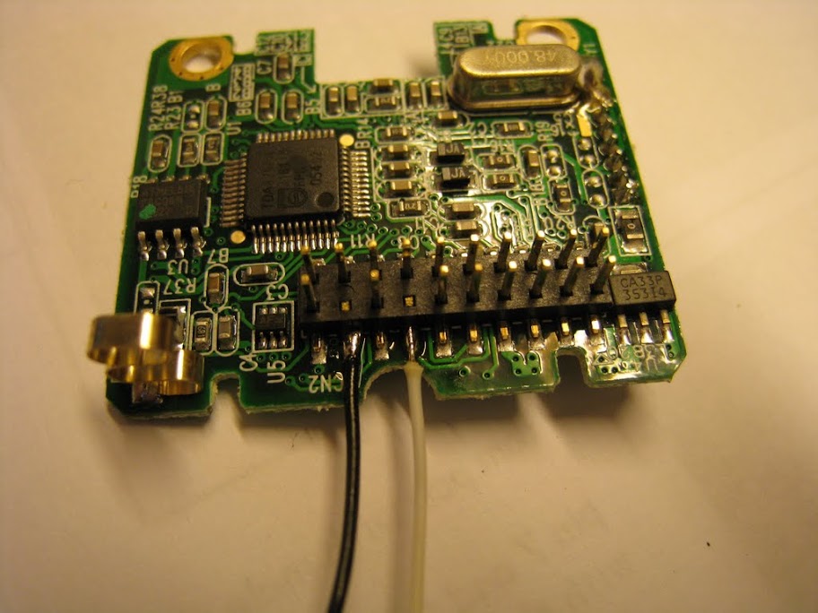
You should end up with this:

Then I use new M3 hex stand-offs to assemble the camera again and provide mounting points on the front. First 2 10mm stand-offs.
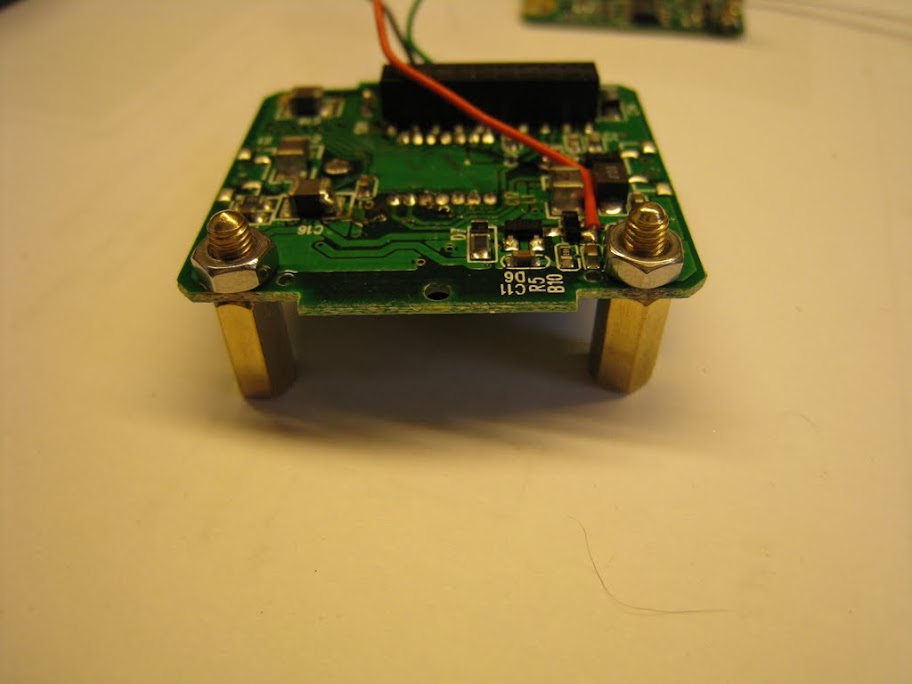
Be very carefull not to touch or damage that capacitor next to the nut on the right hand side.
Then on top of that 2 5mm stand-offs.

Then connect the 2 boards again and finally use 2 nuts to hold it in place.

OK, that's the camera module ready.
Putting it all together
Now, to finish it, we need to connect the camera module to the LX circuit, the camera USB connector to the USB hub, the USB cable to the hub input and the 2 wires to the switch. And finally put everything in the box.
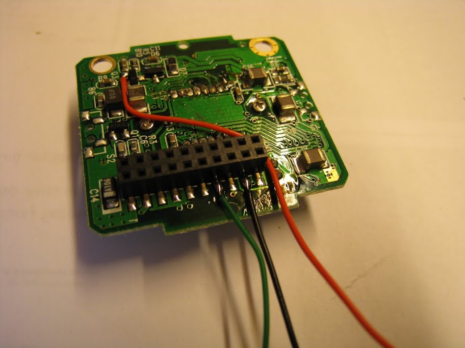
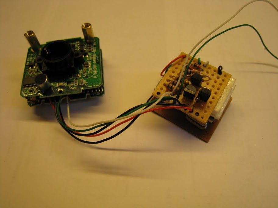
First solder the wires from the camera to the LX board according to the diagram at the top.
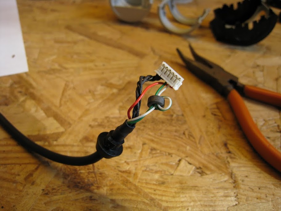
Then remove the webcam USB cable from the plastic housing. Use pliers to turn it 90 degrees and it will come out.

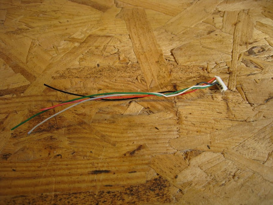
Then cut off the last bit with the plug. The length must be enough to reach from the webcam USB connector to the USB hub solder points. Give it an inch more, just in case.
Strip the insulation off the cable and cut off the shield from the plug.
Then solder that to one of the other USB ports.

Next strip some of the insulation off the remaining USB cable. Keep some of the shield (the 5th "wire" in the picture) and cut off the rest.

I like to make things nice and safe, so I use some heat shrink.

Solder that cable to the input side of the USB hub.
This should now look something like this.

For the final steps I put the camera module in the box and fasten it with 2 screws from the front.

Then I put in the other electonics next to it and use one of the silver side panels of the original webcam enclosure to keep the circuits apart.

Then I solder the 2 wires to the switch. Again, a bit of heat shrink can't hurt.

Put the lid on the back and we're done.

I then add a label indicating the switch positions. The LX mod is disabled (normal mode) when the switch is in closed position.

And that is it. Time to plug it into the computer and test.
