INA3221-R010
Introduction
This is an improved version of the commonly available INA3221 3-channel voltage and current sensor breakout board.
This version has 0.01 Ohm (R010) sense resistors. See here for the version with 0.1 Ohm (R100) sense resistors and here for the version with no sense resistors populated.
Description
The main problem with the original breakout board is that all 3 channels use the same power supply. This version implements the example circuit from the INA3221 datasheet and therefore allows 3 different power supplies; one per channel. All 3 power supplies must have a common ground (GND).
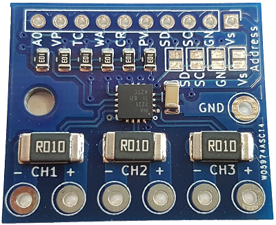
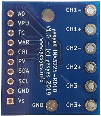
This version also has much larger power tracks and a smaller PCB size (30x26mm). The interface header pin-out is the same as on the original module and adds the VPU pin and the A0 address pin to the header. The latter can be used to set the I2C address of the module externally. This version does not have the LEDs of the original module to save power and PCB space. This can be implemented externally, if required.
The INA3221-R010 version comes with 0.01 Ohm (R010) sense resistors with 1% tolerance, instead of the 0.1 Ohm resistors on the original module. This allows higher currents to be measured (theoretically up to 16A but track size limits this to about 5A) and has only 10% of the voltage drop of the original module. The downside is that the resolution of the current measurement is lower (4mA). I'm also offering an INA3221-R100 model that has 0.1 Ohm resistors, just like the original module, and an INA3221-RNONE model with no sense resistors populated. Otherwise these modules are identical..
Specifications
| Size | 30 x 26mm |
| Supply Voltage | 2.7 - 5.5V |
| Supply Current | 350 µA typical (INA3221) |
| Sense Voltage | 0 - 26V, 8mV resolution |
| Sense Current | ±16A theoretical, limited to about ±5A by PCB track width, 4mA resolution |
| Sense Resistors | 0.01 Ohm (R010), 1% tolerance, 3Watt |
| I2C Adresses | 4 (0x40 (default) - 0x43) selectable by solder jumper or A0 pin, see INA3221 datasheet |
Thanks to Jesus Garcia there is now an EasyEDA library for this module. You can get it form here:
https://easyeda.com/component/651791a037f0475aa784f09a21e28f00
Where to buy
You can buy this module from my Tindie store

Direct link to this product:
https://www.tindie.com/products/yesyes/improved-ina3221-breakout-3-power-supplies-001ohm/
Usage
The interface side can be used exactly the same way as the original module. There is an I2C bus and 4 status output pins. In addition to the header on the original module, this version also has the A0 address pin on the header. To set the I2C address use either the solder jumpers on the module or the A0 pin on the header to set the address externally. Please refer to the INA3221 datasheet for more information on the status pins and I2C addresses.
Texas Instuments INA3221 datasheet
For Arduino the SDL_Arduino_INA3221 library can be used. The library includes sample code. Since the sense resistors of this version of the module are 0.01 Ohm (and not the default 0.1 Ohm) you need to modify the code to pass 2 parameters when instantiating the SDL_Arduino_INA3221 class. Change
SDL_Arduino_INA3221 ina3221;
to
SDL_Arduino_INA3221 ina3221(INA3221_ADDRESS, 0.01F);
The first parameter is the I2C address of the INA3221. The second parameter is the value of the sense resistors in Ohms (the 'F' forces it to be a float value).
Example Circuit
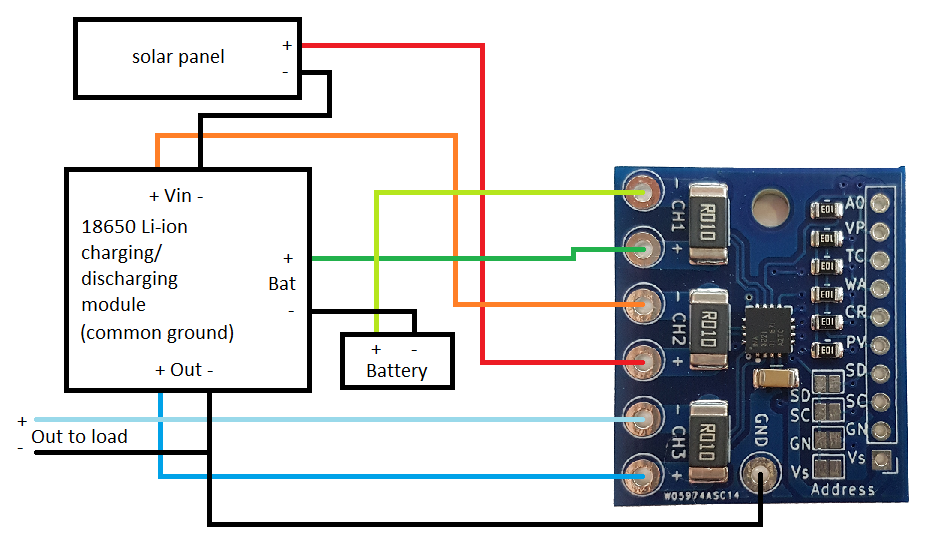
One example use case for this breakout board is to monitor charging / discharging of a Lithium battery by a small solar panel. The following circuit allows to monitor voltage and current from a solar panel, battery voltage and charging/discharging current (positive current = discharging, negative current = charging), and load voltage and current. Please note that the charging module needs to have common ground reference for Vin, Vout and battery.
Photos
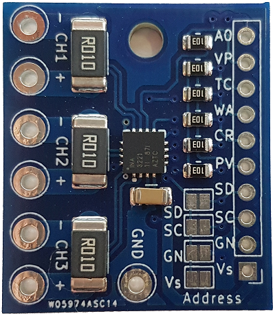
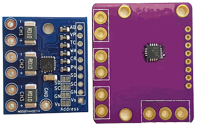
Here are some more photos of the INA3221-R010 breakout board.
Size comparison original module and INA3221-R010 breakout board (images of original module partially blurred to avoid any copyright issues).
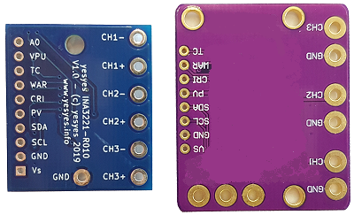
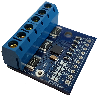
Screw terminals are not included, but this image shows that they do fit.