
ESP-BO-3V3
Introduction
This is an unpopulated breakout PCB for ESP8266 modules ESP-07, ESP-08 and ESP-12.
Description
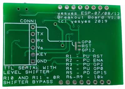
The breakout board contains footprints for all external components needed to run the ESP module and upload your own software to it. In addition it has a serial port header that is pin-compatible with FTDI USB-Serial adapters. The serial port also has level shifters for both TX and RX that can be bypassed with a 0 Ohm resistor (or just a solder bridge across the resistor pins). This allows the use of a 5V USB-Serial adapter even though the ESP8266 requires 3.3V. You would still need to provide separate 3.3V to the ESP in this case.
The serial port header also has an additional pin (DTR pin on the Serial adapter) that can be routed to GPIO_0, GPIO_12 or RESET with a solder bridge on the back of the breakout board.
There are positions for a slim-line 2-pin reset button and a small SMD switch that pulls GPIO_0 low to put the ESP8266 in programming mode.
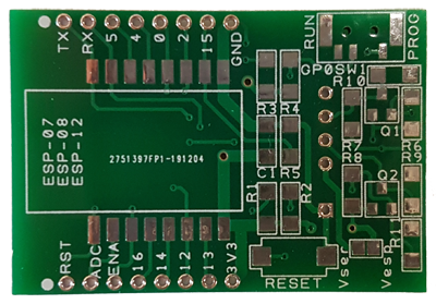
All ESP module pins (except additional pins on the short edge on ESP12) are available in standard, breadboard-friendly 2.54mm / 0.1in pitch on the edges of the PCB in the same order as on the ESP module. However, the PCB is too wide to fit on a small, narrow breadboard. You need either a wide breadboard or use 2 slim breadboards next to each other. See pictues below.
The size of the PCB is 44 x 30mm.
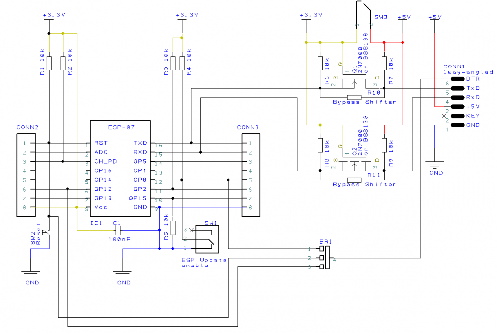
Here is the circuit diagram of the breakout board:
Where to buy
You can buy this module from my Tindie store

Direct link to this product:
(coming soon)
Usage
required components:
- ESP-07, ESP-08 or ESP-12 module
- 1x 100nF capacitor, SMD 1206 (C1) (bypass capacitor for ESP module)
- 5x 10k resistors, SMD 1206 (R1 to R5) (pull-up / pull-down resistors, you may want to use different values, 10k works fine for me)
optional components:
- slim 2-pin reset button (3.5mm wide, 6mm long without pins, 8mm with pins, I did not find a model number)
- SMD switch MSK-12C02 (pulls GPIO_0 to GND to put the ESP8266 in programming mode)
- 2x 2N7000 or BSS138 SOT-23 MOSFETs (Q1 and Q2) if you want to use the level shifter
- 4x 10k resistors, SMD 1206 (R6 to R9) if you want to use the level shifter
- 2x 0Ohm "resistors" / links, SMD 1206 (R10 and R11) to bypass the level shifter, if you don NOT want to use it (alternatively you can solder-bridge R10 and R11)
- 6-pin angled header connector for serial port