
RF1100-232 RF 433MHz Transceiver Module
I have recently started using the RF1100-232 module in an Arduino based project. I found it really difficult to find any useful detailled information on this module. The only info to go on was a document I found on some Russian website that appeared to be a machine translated version of the command table that is otherwise only available in Chinese. This really is a shame as this module is some very useful piece of technology.
So I on this website decided to collect all the information I have found out in the hope that it will be useful for others who are also thinking about using this module.
What does it look like?
It looks exactly like this:
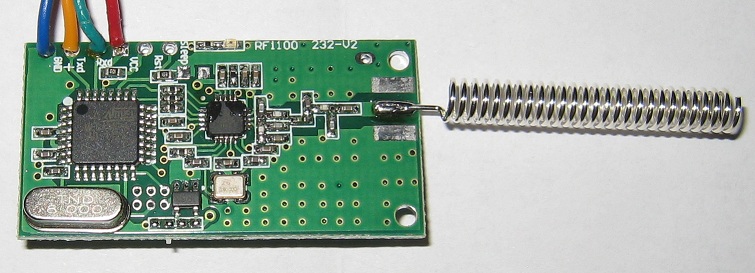
This is the spring antenna version. It is also available with an SMA connector.
The dimensions are 41mm x 21mm (without antenna or SMA connector).
Update:
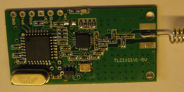
Newer modules I have received are now labelled TLC1101V1-5V and have slightly different PCB layout; most notably the ISP header next to the big X-tal is no longer layed out in a nice 2x3 matrix and the Sleep and Reset pins are reversed. The functionality seems to be exactly the same and my configurator application works fine with these modules. They now look like this:
What does it do?
The module allows wireless transmission of serial port data. The connectors on the module are a TTL-Level (5Volt) serial port and the 5Volt power supply for the module.
The module will transmit wirelessly the data it receives on the Rx input line. And data received by the module will be sent out the Tx line.
The module supports baud rates of 4800, 9600 and 19200 bit/s. 256 individual channels can be selected.
Now, the really interesting part is that this module also supports point-to-multipoint transmission. This means that, when one module is transmitting data, *all* other modules that are on the same channel and within range will receive the same data.
Known Problems
- the sleep mode is not implemented, i.e. the Sleep pin does nothing
- Some of my modules "forget" some of their settings occasionally
Connecting the RF1100-232 module
The module requires a 5Volt power supply. Connect GND of your power supply to the GND pin on the module and the 5Volt of your power supply to the Vcc pin on the module.
The serial port on the module is a TTL level port. This means it uses 0Volt and 5Volt levels. It also seems to work fine with 3.3Volt levels. DO NOT connect the serial port on the module to a normal COM port that uses RS232 levels! These COM ports use up to +-15V levels and would damage the module!
If you use a USB to serial converter, make sure you are using one with TTL levels. The module also works fine when connected to the TTL level serial port on an Arduino.
The following picture shows the RF1100-232 module connected to a FTDI USB to serial converter. Please note that you need to connect Tx on one side to Rx on the other side and vice-versa.
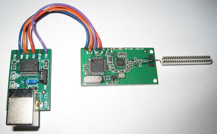
This is in fact all you need for a "base station" that connects to a computer via USB. It gets its power from the USB port.
RF1100-232 command table
Set serial port baud rate
| Text | Command Code | Baud Rate | Description |
| Length | 2 bytes | 1 byte | 0x01: 4800 |
| Format | hex | hex | 0x02: 9600 |
| Fixed | 0xA3, 0x3A | 0x01/0x02/0x03 | 0x03: 19200 |
Example: sending 0xA3, 0x3A, 0x03 to the module sets the serial port baud rate to 19200.
Set channel communication rate (not supported/implemented according to the documents I found)
| Text | Command Code | Channel Rate |
Description |
| Length | 2 bytes | 1 byte | |
| Format | hex | hex | |
| Fixed | 0xA5, 0x5A | 0x64 | |
Set channel
| Text | Command Code | Channel Number |
Description |
| Length | 2 bytes | 1 byte | Channel number from |
| Format | hex | hex | 0x00 - 0xFF |
| Fixed | 0xA7, 0x7A | 0x00-0xFF | (256 channels) |
Example: sending 0xA7, 0x7A, 0x10 to the module sets the channel to 16 (0x10 hex).
Set module ID
| Text | Command Code | Module ID |
Description |
| Length | 2 bytes | 2 bytes | 2 bytes module ID |
| Format | hex | hex | 0x0000 to 0xFFFF |
| Fixed | 0xA9, 0x9A | 0xFF, 0xFF |
|
Example: sending 0xA9, 0x9A, 0x00, 0xFF to the module sets the module ID to 255 (0x00FF hex).
Set TX power
| Text | Command Code | TX Power |
Description |
| Length | 2 bytes | 1 byte | transmit power (dbm) |
| Format | hex | hex | 0x00, 0x05, 0x07 |
| Fixed | 0xAB, 0xBA | 0x00/0x05/0x07/0x0A |
or 0x0A (10 decimal) |
Example: sending 0xAB, 0xBA, 0x0A to the module sets the TX power to 10dbm.
Read config from module
| Text | Command Code | Returned Data Format | |||||
| Length | 2 bytes | 1 byte | 1 byte |
1 byte | 1 byte | 1 byte | 2 bytes |
| Format | hex | hex | hex |
hex | hex | hex | hex |
| Fixed | 0xA6, 0x6A | 0xA6 |
Channel |
Channel Rate | Baud rate | Power | Module ID |
Example: sending 0xA6, 0x6A to the module returns the following data containing the module's current config:
0xA6, 0x10, 0x64, 0x03, 0x0A, 0x00, 0xFF
0xA6 - start of config dump (fixed)
0x10 - Channel number 16 (0x10 hex)
0x64 - Channel rate (fixed)
0x03 - 19200 baud
0x0A - 10 dbm TX Power
0x00, 0xFF - 2 byte module ID
Unlike the more familiar AT commands, these commands have to be sent as binary, not as ASCII text. So you can't just use any standard terminal program.
That's why I have written a nice little application that lets you send these commands to the module.
The RF1100-232 Configurator
This is a little program I wrote that allows you to configure a RF1100-232 module with a few mouse clicks. You can also monitor serial communication in hex or in ASCII and send data to the module; also in hex or ASCII. The download link is at the bottom of this page.
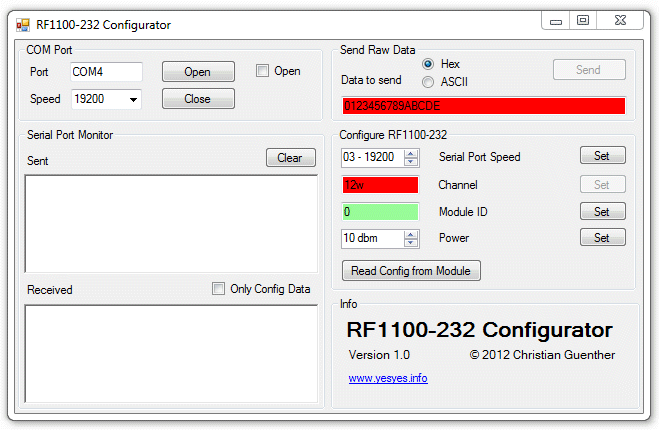
Here is what the interface looks like:
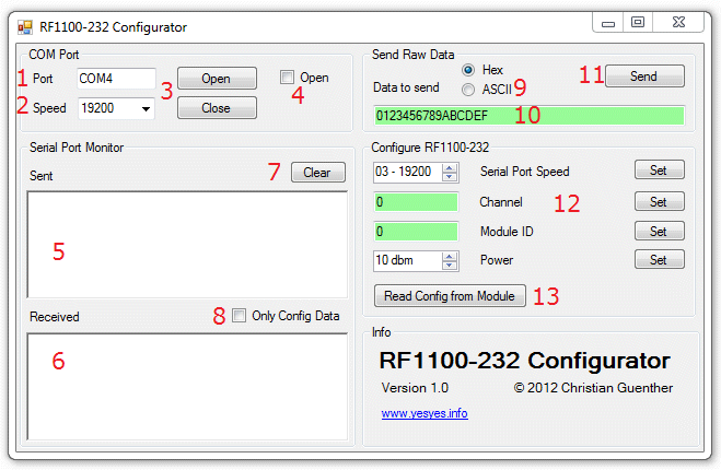
1 - Enter the COM port name the RF1100-232 module is connected to.
2 - Select the serial port speed that the module is currently set to. You can select the 3 speeds that the module supports (4800, 9600 and 19200) from the drop-down list or type any speed in the text box.
3 - The Open and Close buttons open or close the COM port. If you have changed a setting in the COM Port Group (COM port name or speed) and want to apply this setting, just click Open again. This will first close the COM port if it was open, then open it with the new settings.
4 - This checkbox indicates whether the COM port is currently open (checked) or closed (unchecked). This is informational only, you can't click on the checkbox.
5 - This text box will display anything that has been sent from the application to the module, either raw data or configuration commands.
6 - This text box will show data received by the module. This will include any data transmitted between any other modules on the same channel and within range. This allows this program to be used as a data sniffer for troubleshooting communication between other modules.
7 - The Clear button clears the data in both text boxes.
8 - When this checkbox is checked the Receive text box will only show the module's responses to config commands, not any other received data. This can be useful when there is a lot of traffic in the air.
9 - Here you can select whether you want to send raw data to the module in hex or ASCII format. This option also influences the way that any received data is being displayed in the Received text box (6).
10 - Enther the data to be sent to the module here. When (9) is in hex mode you can only enter pairs of hex digits (0-9, A-F), each pair representing 1 byte. If there is an error in the text box (odd number of digits or non-hex digits), the background of the text box will turn red and the Send button will be deactivated. The data will be send to the module in binary format. In ASCII mode there are no restrictions on the text you can enter. The data will be send to the module as ASCII encoded text.
11 - Clicking the Send button sends the entered data to the module in either binary or ASCII format.
12 - Here you can configure the module and send the configuration commands individually. Select the serial port speed (4800, 9600 or 19200), channel number (0 - 255), Module ID (0 - 65535) or TX power (0, 5, 7 or 10 dbm). Then click the corresponding Set button to send the command. If you set the serial port speed of the module, the COM port will automatically be set to the new speed. The Channel and Module ID text boxes automatically check the validity of the entered values as you type. If there is an error, the text box background will turn red. If everything is OK, the background will change to pale green. (see screenshots above and below)
13 - This button allows you to read the current config from the module. The results will be populated in the parameter boxes above (12).
The following is a screenshot showing invalid data in 2 text boxes. Text box (10) has an odd number of digits and text box Channel has an invalid character w.
Change log
V1.0 - 28/02/2012
initial release.
V1.1 - 01/08/2012
Channel and Module ID can now also be entered in hex format with a 0x prefix as shown in this screenshot. Without the 0x prefix the number is interpreted as decimal.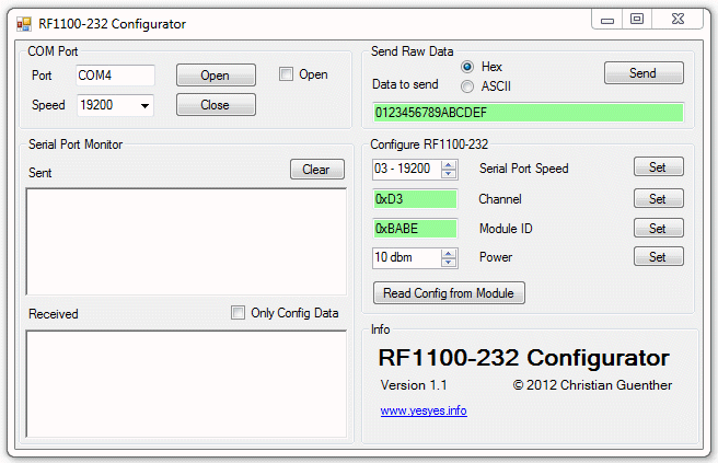
Download
This software is provided as freeware.
Of course the usual disclaimer applies. This software is provided as-is with no warranties whatsoever. In other words, I'm not responsible if you break or damage anything by using this software. Use it at your own risk.
You need to have Microsoft .NET 4.0 installed to run this software.
Length 2 bytes 2 bytes 2 bytes module ID
Format hex hex 0x0000 to 0xFFFF
Fixed 0xA9, 0x9A 0xFF, 0xFF
Example: sending 0xA9, 0x9A, 0x00, 0xFF to the module sets the